Alignment tools
To perform the alignment you will need a magnetic indicator stand and a lever style test indicator that reads at least to .01mm or .0004", hex wrenches both 5/16" and 3/8", some plastic and steel feeler gauge stock. In addition will be several pins to help hold the shaft from turning, and some washers to replace the thickness of the moving wiper when installing the bottom burr driver to perform the burr wobble test. It is best that you would also borrow or buy a torque wrench and hex sockets to suit. A better stand and indicator will be handier but will add considerable to the cost.
• Inexpensive stand and indicator.
eBay <$22 free shipping. It can measure to .01mm (.00039"). This suffices to get the job done.
https://www.ebay.com/itm/Universal-Flex ... 2749.l2649
• Better stand and indicator
From shars.com measures to .0001". Requires a better stand with fine adjustment since the measuring range is reduced.
sku 303-3210A indicator ~ $46 on eBay or $58 direct. On eBay search on Shars .008
sku 202-6021 stand $23.35 direct
• Torque wrench
$46 for the wrench and $12 for the sockets - from Amazon
eTORK (C2250) 3/8-Inch Drive"Click Style" Torque Wrench (50-250 Inch lbs./60-280 dN.m)
TEKTON 1375 3/8-Inch Drive by 3/8-Inch Hex Bit Socket, Cr-V
TEKTON 1374 3/8-Inch Drive by 5/16-Inch Hex Bit Socket, Cr-V
How to get started!
Versalab will provide the following. Basically at the cost price [including shipping price to us] plus a little money to cover our time putting this together.
• Alignment tool kit $42 + shipping
Includes cheap stand and indicator, two hex wrenches, feeler gauges, pins and washers
• Optional torque wrench additional $58 + shipping .
This is the torque wrench listed above plus the two necessary hex sockets.
If you are buying the tools yourself instead of from Versalab, you should still let us know so that we can supply the feeler gauges. There will be a steel .004"and .030" piece for several alignments and three each of .002" and .004" plastic for centering the bottom burr. Plus two pins for holding the center shaft and some washers to make up for the uninstalled moving wiper. $9 for these + postage.
If you prefer the more expensive stand and indicator please purchase them yourself.
Please let us know by email what you would like to do. We will want payment at order, and we will wait for three orders before we will source the tools. If time drags on waiting for three orders, we will go ahead with less orders.There are quite number of YouTube videos showing how to use these devices.
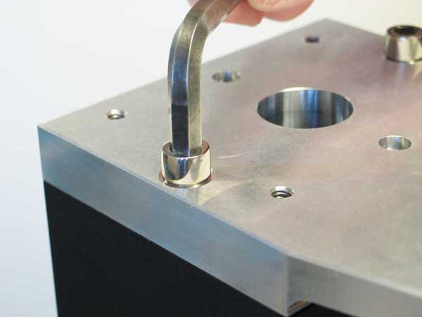
•• To begin, remove the power cord, and lay the grinder on its back. Remove the bottom funnel using the 3/16” hex wrench that came with the grinder (or in the case of the earlier grinders 1/8” wrench for the button headed screws).
When doing this, be extremely careful to move the funnel down toward the baseplate so as not to touch the moving wiper. The wiper is made to exacting tolerances and can’t be repaired in the field. If it becomes bent it will allow an excess of grounds left in the grinder or falling out as a large clump.
Then remove the wiper with the same wrench. In the case where the measurement requires the burr driver or bottom burr to be in place use the supplied washer to replace the moving wiper. Be careful about removing the burr driver if the unit is upright. The inner conical is right above it and can fall down damaging the baseplate.
All this is covered in the User’s Manual with regard to changing burrs. If you don’t have one let us know and we will email a .pdf to you. We are at revision 10 so knowing your serial number will be helpful to us getting you the correct manual.
In some cases the grinder is best on its back and in some standing upright.
There are four types of burr misalignment. We have chosen an order with which to go about checking and rectifying any misalignment.
1. Constant angular offset
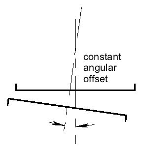
In this first case the error exists in a way that can’t be fixed in the field. We have not seen a case like this, but we feel we must accept that it might exist, especially if the machine was poorly packed for shipping, and dropped.
The test is to raise the top funnel enough to get a feeler gauge in the gap between the top and bottom flat burrs and then lower the funnel so the top burr is just touching the gauge. Lock the funnel with the adjustment lock knob. Move the feeler gauge around the gap to see if there is a variation in the gap.
Using a largish feeler like .030” or so will help make this easier.
2. Angular runout
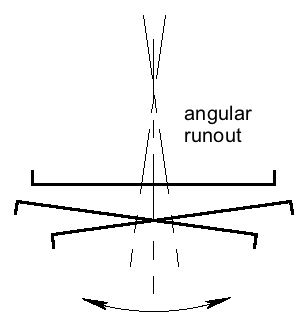
As the drawing indicates the axis of the center shaft is not constant. The shaft isn’t loose (although it could be) but what we mean is that the bottom end of the shaft describes a circle. This will cause the gap between the two flat burrs to vary once a revolution and possibly further prevent them from getting close enough to make espresso much less Turkish. The shaft needs to revolve in the bearings so that it has less than .003 radial run out - measured at the bottom end.
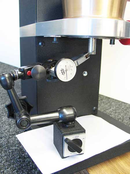
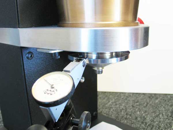
Put the indicator into the magnetic stand and place it on a piece of paper (to protect the paint) on the baseplate, setting the magnet to hold it in place. Adjust the stand and indicator such that the lever of the indicator touches the end of the shaft and that the motion of any error moves the lever at 90º to the lever pivot on the indicator body.
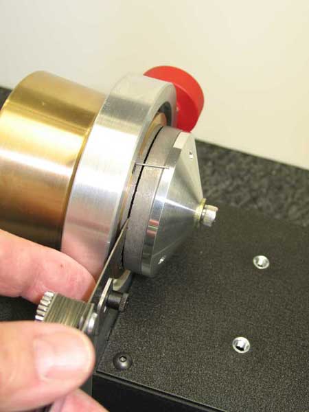
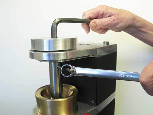
If there is more than .003” run out, loosen the top pulley bolt, and by hand slowly move the shaft to run more true. Don't apply too much force, firm pressure is fine. You are subtly modifying the position of the top of the shaft in the bearings.
Slowly tighten the pulley bolt while checking and readjusting if necessary. The bolt should then be torqued to 150 inch pounds.
Shown here is one way of loosening the pulley bolt. Using the wrench on the dowel pin - to hold the shaft still - is a handy procedure.
This entire section pertains to M3 grinders made before 2013. Serial numbers before 327 - with the exception of 331. All subsequent grinders will not have any alignment issues unless damaged.
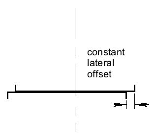
3. Constant lateral offset
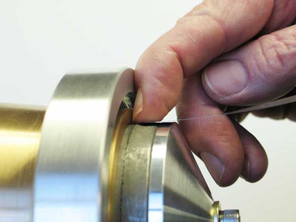
Before checking this lateral offset, use the supplied plastic shim strips to center the bottom burr on the burr driver. We have found that the clearance and tolerance of the inner diameter of the bottom flat burr sitting on the burr driver leaves the bottom burr open to being eccentric. We are supplying .002” (.051mm) and .004” (.10mm) plastic shim. Cut three small pieces, loosen the three screws, insert the thickest that will fit - roughly 120º apart, tighten the screws and remove the strips. Obviously, the three shims should all be of the same thickness.
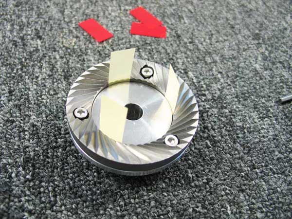
Reinstall the burr driver using the screw and washer. Screw the top funnel down so that the top and bottom burrs are close. Be certain that there is a tiny amount of gap so that you can freely rotate the shaft. Rotate the center shaft and observe the two burrs. Look for an offset such that the outer edge of each burr does not line up with the other. The maximum gap should be on the order of a few thousandths of an inch. You can probably make a close adjustment just by eye, and use the fingernail test as described in the next paragraph.
If there is an offset, find the position where the bottom burr is underneath the top burr - as where the arrows are in the drawing above. Using one of the feeler gauges hold it against the bottom burr and using a fingernail or credit card (or similar) move it across the gap between the two burrs. If there is a hitch (click) moving upwards then the feeler gauge is smaller than the error, and there should be no hitch or click moving your fingernail down across the two burrs. This should be a simple obvious test. We found that we can tell easily .0015 - .002”.
To remove the offset it is necessary to loosen the top frame bolts with the 5/16” hex wrench. They should be just barely loose enough that you can shift the relative positions of the top and middle plates. Notice that moving the top plate moves the bottom burr not the top burr!
As always, tighten the bolts a little at a time rechecking the alignment as you go. Tighten the bolts alternatively.
4. Wobble of burr
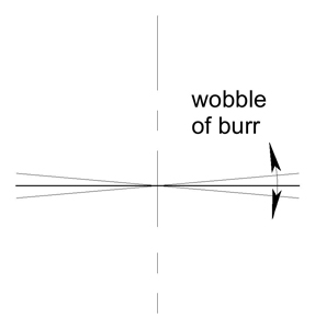
The design of the grinder is such that the shaft should have a face machined very true to the axis of the shaft. Then the inner conical burr is ground on both faces making the ends extremely parallel, And the burr driver faces that seat against the inner conical and the back of the bottom burr are also extremely parallel. Once assembled the bottom burr should then run without any wobble, or so called axial run out.
This test comes after getting the shaft itself to run true to .003” total run out.
Remove the bottom burr from what we call the burr driver. Clean the top and bottom of the inner conical, the face on the shaft that the inner conical seats against, and both the burr seat and the inner conical seat of the burr driver. Assemble the inner conical burr and the burr driver [without burr] onto the bottom of the shaft and fasten with the screw and supplied washers.
Once again mount the indicator and stand on the baseplate remembering the paper for paint protection. Set the indicator so that the face of the indicator is easily visible and the lever rests on the burr seat such that the lever is parallel to that face. Have the end of the lever close to the edge of the burr driver so that it doesn’t fall into the burr screw holes, but not so close to the edge that it does not read the face.
With the shaft running that true, the face of the shaft that the inner conical fits against should be equally running true since all those surfaces are machined together. The inner conical should show signs that both end faces were surface ground. So providing the shaft and top of the inner conical are clean and free of surface protrusions (burrs) the bottom of the inner conical should run as true as the face of the shaft.
Any small imperfection on these faces will cause the outer edge of the burr driver to wobble.
